
CO2 As A Refrigerant? Part 2
July 19, 2022 | By Dave Demma
Re-visiting the return of CO2 as a refrigerant solution for supermarket applications.
In the March 2022 issue of HPAC I wrote about the re-emergence of CO2 as a refrigerant being used in supermarket applications in North America. I’ve returned to share more on the subject, specifically some of the key differences between a CO2 system and our more common HCFC/HFC refrigerant systems in place today, and also to share some potential system set-ups required to work with CO2.
CO2 Differences
1. Higher Pressures: while CO2 pressures are higher than those experienced with HCFC/HFC refrigerants, this is not the first refrigerant to enter the marketplace with substantially higher pressures than the industry’s mainstay refrigerants.
See Table A below for a comparison between former mainstay refrigerants and the new refrigerant designed to replace it. The most recent example of this would be the higher pressures seen in an R-410A system as compared to an R-22 system. While it’s not of the same magnitude as the increase between CO2 (R-744) and R-404A, it’s still a good example.
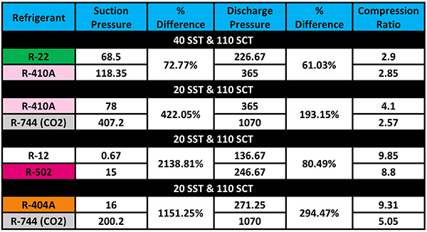
Table A. Pressure comparisons between refrigerants.
2. At a given saturation temperature, the CO2 pressure will be substantially higher than HCFC/HFC refrigerants. For example, at a -20F SST, the corresponding pressure will be 200 PSIG. Because of the higher pressures, you may see Type K copper, steel, stainless steel, or hybrid copper-steel piping, depending on the application.
For example, the maximum allowable working pressure for the CO2 LT Secondary system is 400 PSIG. This would be the rating for the system relief valves. As such, the copper tubing will need to have a MAWP rating of at least 400 PSIG. The 1-⅝-in. and 2-⅛-in. Type L copper tubing does not meet that rating, requiring Type K to be used for those two sizes. (see Table B below)
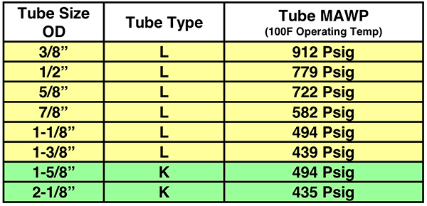
Table B. Pipe requirements CO2 secondary.
3. The CO2 might be used as a secondary heat transfer fluid.
4. Insulation wall thickness will be 1-in. in mild conditions (80F dry bulb, 50% RH), 1-½-in. in normal conditions (85F dry bulb, 70% RH), and 2-in. in severe conditions (90F dry bulb and 80% RH).
5. Piping in display cases must be insulated.
6. Available in several different purity grades (as opposed to a single grade for HCFC/HFC refrigerants). The Coleman Grade, with a purity of 99.99%, is the recommended minimum grade for refrigeration applications.
7. CO2 has a greater volumetric cooling capacity as compared to common HFCs. For example, in a -20F application, R-404A has a latent heat of vaporization of 81 Btu/lb-min. In the same application CO2 has a latent heat of vaporization of 130 Btu/lb-min. The resulting mass flow requirement for CO2 will be approximately 38% less, with the benefit of smaller compressor displacement and smaller pipe sizes.
8. Due to the high operating pressures you will see more pressure relief valves. Anyplace in the system where liquid CO2 could be trapped with an isolation valve closure will require a relief valve piped in parallel. This allows a flow path for the potential high pressure CO2 in the isolated portion of the system to vent back to the main receiver vessel.
9. System Charging: after evacuating, break system vacuum with vapour only. The triple point occurs at 75 PSIG, charging liquid into a system which is at a pressure less than 75 PSIG will allow triple point conditions, meaning that some portion of the liquid will turn into a solid. This is known as deposition (or desublimination). It would certainly be unfortunate if dry ice were to form inside the system piping during charging. The system should be pressurized to somewhere between 200 PSIG to 250 PSIG to avoid this scenario.
Definitions
In the previous article I covered a series of important definitions including: critical point, critical temperature, critical pressure, triple point, sublimation, subcritical and transcritical.
Before we walk through four types of CO2 systems that might be present in a new application, let’s cover a few more system-related definitions:
- Direct Expansion: A refrigeration system which includes a compressor, condenser, evaporator coil and some variety of expansion device.
- Primary Refrigerant: A refrigerant which is used to lower the temperature of a secondary heat transfer fluid. For example, R-407A or R-448A could all be applied as a primary refrigerant.
- Secondary Heat Transfer Fluid: A fluid used to transfer heat from the refrigerated space to the primary refrigerant.
- Single-Phase Secondary Heat Trans-fer Fluid: A secondary fluid which absorbs heat by experiencing a sensible heat gain (temperature increase, but no change of state)
- Two-Phase Secondary Heat Transfer Fluid: A secondary fluid absorbs heat by experiencing a latent heat gain, resulting in change of state.
- Cascade System: A system having two (or more) refrigerant circuits, where the evaporator of one circuit provides the heat transfer capacity necessary to accomplish condensing in the second circuit. The cascade evaporator/condenser will typically be of the brazed plate heat exchanger type.
- Upper Cascade: The refrigerant circuit in the cascade system which provides heat transfer capacity to the condenser in the second circuit. The heat transferred to the refrigerant in this system is rejected to some type of heat sink, typically an air cooled condenser, evaporative condenser, or water cooled condenser.
- Lower Cascade: The refrigerant circuit in a cascade system which transfers heat from the refrigerated spaces, and transfers that heat to the upper cascade.
CO2 Secondary – Liquid Overfeed System
This system will use a separate direct expansion system, whose purpose is to maintain a secondary heat transfer fluid at a specific temperature. It is similar in concept to a chiller system cooling down propylene glycol, which is then pumped to the various display cases and walk-in boxes, and used as the medium to transfer heat from those refrigerated spaces. The obvious difference being that CO2 has replaced the propylene glycol as the secondary fluid.
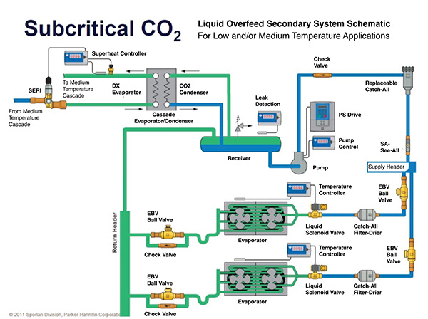
Figure 1. CO2 Secondary – Liquid Overfeed System.
Why bother using CO2 for this application?
Glycol has been used with success as a secondary fluid in medium temperature applications. While a second stage of heat transfer will add some inefficiency, because the chiller negates pumping refrigerant to each display case and walk-in box, it does allow a huge reduction in refrigerant charge. Unfortunately, glycol is not suitable as a secondary fluid for low temperature applications. So, this method of reducing the refrigerant charge has not been an option for low temperature systems.
CO2 allows secondary systems to become a viable option for low temperature applications. As opposed to the sensible heat transfer process which propylene glycol offers, CO2 offers the added heat transfer benefit of a fluid experiencing a change of state, which makes it a more efficient process. This, plus the fact CO2 has a greater volumetric cooling capacity, will allow for the use of smaller pipe sizes.
Figure 1 (above) shows a typical piping/component diagram for a CO2 Secondary – Liquid Overfeed System. This being a cascade system, an HFC system will provide the heat transfer capacity necessary to condense the CO2 vapour into a liquid. Note that the lower cascade (the CO2 portion) does not use a compressor.
We’ll start at the Liquid Vapour Separator, which receives the liquid/vapour mixture returning from the evaporators, and separates the two phases in the vessel.
Liquid from the bottom of the vessel enters the pump inlet, which provides necessary pressure differential to supply liquid CO2 to the various evaporators connected to the system. As with any other refrigeration system, a main liquid filter-drier will be used to remove harmful contaminants from the CO2. From there, the CO2 enters a liquid header, where individual liquid circuits will supply CO2 to each evaporator.
This is a liquid overfeed system where the CO2 flowing to the evaporators is already at the design SST. As such, no expansion device is required.
In addition, the evaporators are circuited for the overfeed application. A solenoid valve at the inlet of the evaporator, controlled by either a standalone temperature controller, or the system’s central energy management controller, will regulate the flow of CO2 to each evaporator.
When the temperature is above the set-point, the solenoid valve coil will be energized, allowing the valve to open. Liquid CO2 will flow through the evaporator, changing state as it absorbs heat from the refrigerated space. A mixture of liquid and vapour CO2 will flow back to the Liquid Vapour Separator, with the liquid settling to the bottom, and the vapour rising to the top.
The cooler temperature occurring in the cascade evaporator/condenser will facilitate the flow of vapour from the separator to the condenser, resulting in a change of state from vapour to liquid, replenishing the liquid supply in the separator.
CO2 LT Direct Expansion Cascade – Subcritical
Think of this as a typical vapour compression cycle, with CO2 as the refrigerant in the system. The only difference between a standard vapour compression cycle and the DX Cascade – Subcritical system is the fact that the heat transfer capacity necessary to condense the high temperature/high pressure vapour leaving the compressor into a high pressure/high temperature liquid is provided by an HFC refrigeration system, with the heat transfer taking place in a cascade evaporator/condenser (Figure 2).
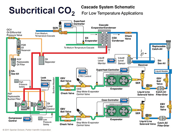
Figure 2. CO2 Low Temperature Direct Expansion Cascade – Subcritical System.
Starting at the compressor: low temperature/low pressure vapour flows from the evaporators to the suction manifold, where it is then dispersed to whichever compressors happen to be operating at any given time.
The compressors will compress the vapour, with a high temperature/high pressure vapour exiting the compressor. As common in a typical HFC multi-compressor rack, the discharge vapour flows to an oil separator before entering the condenser.
Again, the main difference in this system is that rather than a traditional condenser, the discharge vapour enters the cascade evaporator/condenser. Here the HFC system provides the heat transfer capacity necessary to condense the CO2 discharge vapour mass flow into a liquid.
From here on, the system is nearly identical to a standard HFC system, with the liquid refrigerant flowing into a receiver, through a filter-drier and sight glass, then onto a liquid header.
Here the individual system branches are supplied liquid as necessary. Electric expansion valves have become a standard feather in LT CO2 applications, taking the high temperature/high pressure liquid and allowing it to experience a pressure drop to bring the liquid to the design SST.
The liquid vapour mixture enters the evaporator, absorbing heat from the refrigerated space, and fully changing state into a vapour before the evaporator outlet. In the diagram in Figure 2, an electric suction line regulator is shown as the method for maintaining constant discharge air temperature.
CO2 MT Liquid Overfeed/LT DX Cascade – Subcritical
The system in Figure 3 shows a hybrid system, a combination of the two previously discussed systems.
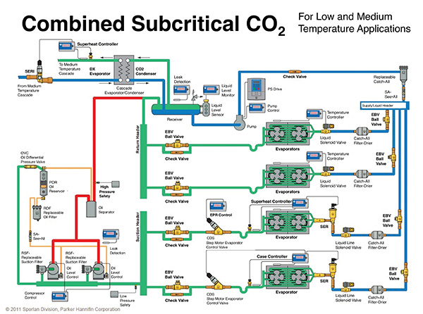
Figure 3 – CO2 MT Liquid Overfeed/LT DX Cascade – Subcritical.
The addition of the MT liquid overfeed portion requires the receiver to be of the liquid/vapour separator design. Liquid from the separator is pumped to both the LT and MT evaporator systems, with the MT operating as flooded evaporators and the LT operating as DX evaporators.
The liquid/vapour mixture leaving the MT evaporators and the discharge vapour leaving the LT compressors are piped together via a tee, and then flow into the liquid/vapour separator. From here, vapour condensation is accomplished as the lower temperature in the cascade evaporator/condenser draws the vapour from the top of the separator.
CO2 Booster – Subcritical/Transcritical System
The final system is the granddaddy of sustainability, as it eliminates the need for any refrigerant other than CO2.
As such, in ambient conditions where the resulting saturated condensing temperature will be greater than 87.9F the system must operate in the transcritical region. Since above the critical point the CO2 will not exist as a liquid, this presents a challenge that must be dealt with by different system design/components (Figure 4).
Figure 4. CO2 Booster – Subcritical/Transcritical.
This is a two stage (compound) compression system, which in principle isn’t unlike the many R-22 two-stage that saw use after R-502 was phased out.
The idea is that compressing the vapour from the low temperature evaporator systems in two stages allows for greater compressor efficiency by reducing the operating compression ratio of all compressors.
Vapour from the LT evaporator systems enter the LT compressors, which raise the low pressure to an intermediate pressure corresponding with the MT vapour pressure. The discharge vapour from the LT compressors flow through an oil separator, and then enters the suction manifold to the MT compressors.
Here, the LT discharge vapour is joined by the vapour leaving the MT evaporator systems, and the entire system mass flow then enters the MT compressors.
The discharge vapour leaving the MT compressors will first flow through an oil separator before entering the gas cooler.
Now, if the ambient conditions are such that the SCT is less than 87.9F, the CO2 vapour will indeed condense into a liquid. In this condition, the system will operate similar to a typical vapour compression cycle, with the liquid leaving the gas cooler flowing into the receiver, and supplying the liquid header as needed.
But for those times when the SCT is above 87.9F, the gas cooler transfers heat from the discharge vapour without a change of state taking place. This “neither liquid nor vapour” mixture enters the flash tank, where the “flash tank bypass valve” will vent the high pressure to the suction manifold of the MT compressors.
This allows sufficient reduction in pressure/temperature to move below the critical point, and allow the CO2 to revert to a saturated condition, with both liquid and vapour phases present. From here, the liquid is supplied to the liquid header, supplying liquid to the various liquid feeds to each evaporator system as needed.
There are a few problems with the transcritical application:
(1) Due to the higher condensing temperature and pressure, the higher compression ratio results in a less efficient compression process;
(2) the refrigerant quality (% vapour) after the expansion process is greater, meaning that greater mass flow is required to provide the same mass flow of liquid at the evaporator inlet; and
(3) some amount of MT compressor capacity is dedicated to bringing the transcritical refrigerant mass in the flash tank back into a subcritical state.
These have the combined effect of reducing the system efficiency, requiring extra compressor capacity to meet the design load condition.
One partial solution against the inefficient transcritical operation would be the addition of an adiabatic gas cooler. Think of a condenser/gas cooler with the incoming air being treated first by an evaporative cooler, to reduce the warm ambient air temperature to a cooler entering air temperature.
Well, there it is, a brief but lengthy overview of various CO2 systems available for sustainable supermarkets. As I stated in Part 1 of this article, the CO2 movement has seen a tremendous increase in Europe and it’s growing in North America. And while I hadn’t been too enamoured with CO2 before, that’s changing. <>
 Dave Demma holds a degree in refrigeration engineering and worked as a journeyman refrigeration technician before moving into the manufacturing sector where he regularly trains contractor and engineering groups. ddemma@uri.com.
